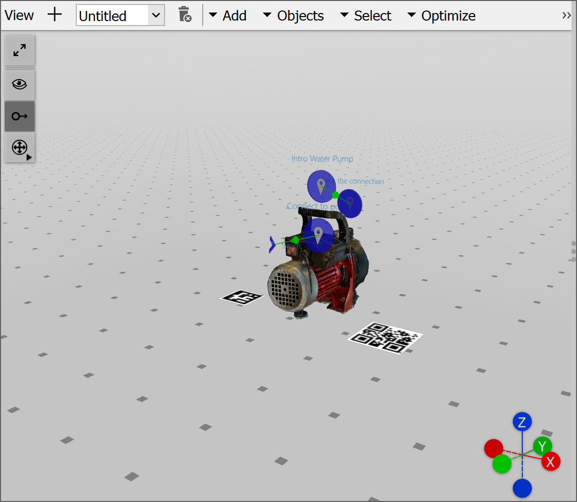
The scene is where the users can view the workflow in 3D.
- Layers: A Layer is a way to help organize workflows for easier editing.
- Add: Enables users to add Markers, Object Tracker, Model Placement, Pin, and Quiz Pin to a workflow.
- Objects: Gives users options to Duplicate, Snap, Hide, Show, Show All Hidden, Isolate, Copy, Paste, and Delete.
- Select: Gives users options to Select All, Deselect All, Deselect All CAD, and Deselect All Items.
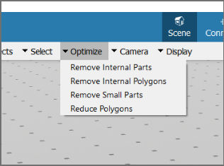
- Optimize: Gives users options to Remove Internal Parts, Remove Internal Polygons, Remove Small Parts, and Reduce Polygons.
- Camera: Gives users options to change the view to Front View, Back View, Top View, Bottom View, Right View, Left View, and Reset Camera.
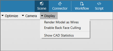
- Display: Gives users options to display model as Render Model as Wires, Enable Back Face Culling, and Show CAD Statistics.
- Show hidden: Makes visible the hidden nodes, models, and model parts.
- Show connections: Shows and hides the connection lines between the pins.
- Transform gizmo: Changes the transformation gizmo settings to Auto, Local, and Global.
- Transformation gizmos: Allows mouse-controlled translation and rotation of parts and items (e.g., pins and markers) inside a 3D scene.
Layers
Layers constitute a way to organize workflow content (such as pins, markers, and other user-created content) in different views. This helps to cluster group elements (such as pins, markers and 3D objects) of a workflow, in various sections or topics. A user can create a layer in which they define which elements are visible and which are not, so that when they select that layer afterwards, all the configuration of the visible/invisible content gets set.
Users can have multiple layers, with each having a purpose. A 'without pins layer' that has all its pins set to invisible or a 'internal parts layer' that has all its pins set to visible and external parts to invisible could be examples. This can be helpful when the 3D Scene of the Editor should be less cluttered with pins.
This differentiation between what is visible and what is not in one layer is only relevant to the Editor. Once the workflow is uploaded to FCC, all layers are merged into one workflow to be played in the Spatial Workplace app.
Note: The 2D Connector does not reproduce the different visibility of items between views. All items are visible in the 2D Connector.
Objects
Objects include the option to modify the existing elements of a workflow:
- Duplicate: Allows users to duplicate any element (nodes or parts of the model) of a project. The duplicate element is created at the same location as the existing one and can be manipulated using the transformation gizmo.
- Snap: Allows users to move the location of the existing nodes, such as the pins, scene states, markers, and conditional nodes, to a new location.
- Hide: Hides the selected elements of the project from the view.
- Show: Shows the selected hidden elements of the project. The hidden elements can be selected from the Scene Explorer.
- Show All Hidden: Shows all of the hidden elements of the project.
- Isolate: Hides all of the elements of the project except for the selected one.
- Copy/Paste: Allows users the option to copy any nodes (pins, scene states, markers, and conditional nodes) and paste them either into the same project or to any other open instance of a project.
- Delete: Deletes the selected element from the project.
Optimizations
Users can use the Optimize menu to reduce the number of parts and triangles. After loading the model, click on Optimize on the top to see the following options:
- Remove Internal Parts: Removes all internal model parts that cannot be seen from the outside. Higher resolutions will produce a more accurate result, while lower resolutions will reduce the part count. If the model will not be inspected up close, consider using low resolutions.
- Remove Internal Polygons: Removes all internal part polygons (triangles) that cannot be seen from the outside. Higher resolutions will produce a more accurate result but take more time. If the individual parts are very dense in polygons, consider using high resolutions to avoid producing cracks in the parts. Otherwise, if the parts are simple or will not be inspected up close, consider using low resolutions.
- Remove Small Parts: Removes small parts based on the given value. A part is removed if all of its dimensions (width, height, and depth) are smaller than the provided maximum dimensions.
- Reduce Polygons: Reduces the polygon (triangle) count via mesh decimation. The polygon target ratio can be used to set the desired target percentage of polygons. The error threshold can be used to stop the reduction if a certain error is reached. A higher threshold would allow more reduction in the cost of quality.
Note: The user can also select the entire 3D model to run the above optimizations.
Once the user has completed mesh decimation on a model, they can assess how the visual quality of the model has been affected. If the model still meets the quality standards, they can then check the number of triangles and make a decision whether to further optimize the model or stop.
However, if the quality of the model has been significantly impacted and it no longer meets the requirements, the user can use the Back function of the editor to revert the effects of the optimization.
3D Model Manipulation
3D models can be quite large and running them on devices with limited capabilities can be challenging. Spatial Editor offers various display options and an optimization feature to address this issue without compromising any functionalities.
Display Options
After loading the model, click on Display to see the following options:
- Render Model as Wires: When activated, the model adopts wireframe mode, displaying only the edges of its faces. This reduces the complexity of the model.
- Enable Back Face Culling: When activated, the back of mesh faces are excluded in the visualization. When the model has been correctly constructed, it will maintain its original appearance while enhancing performance. However, if the model's faces were inaccurately modeled or inverted, it may lead to gaps or holes in the mesh.
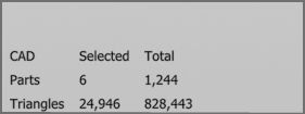
- Show CAD Statistics: When activated, the number of parts and triangles of selected parts in the lower left corner will be displayed. This helps the user make decisions according to the computing power of the device that is intended to be used for the particular workflow.
Transformation Gizmos
The transformation gizmos allow mouse-controlled translation and rotation of parts and items (e.g., pins and markers) inside a 3D scene. It is triggered when selecting one of these elements.
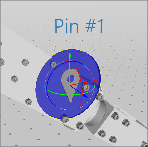
To change the position of an item or part along the selected axis, drag one of the colored arrows with the mouse. To rotate the item or part around one axis, drag the colored circle.
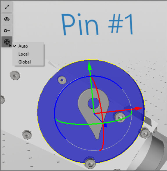
Transformation Space
On the top left menu of the 3D scene, it is possible to switch the transformation space:
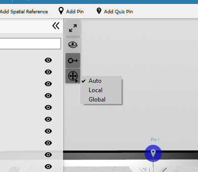
- Auto: Shows a local gizmo if only one item or part is selected and a global gizmo if more than one is selected.
- Local: The gizmo uses the axes of the selected item or part. If more than one item or part is selected, the gizmo will show the axes of the one being selected first.
- Global: The gizmo uses the axes of the whole scene.
Note: Items can only be selected together with other items and parts can only be selected together with other parts.
The scene's axes are shown in the bottom right corner of the 3D scene.
Note: If the transformation axes–red, green, and blue axes when selecting objects in the 3D scene–are rotated in an unexpected orientation, try to toggle the transformation space to Local or Global in the shortcut menu on the left side of the 3D scene view.